

High-Voltage Disconnector Switch 126kv
-
Price:
Negotiable
- minimum:
- Total supply:
-
Delivery term:
The date of payment from buyers deliver within days
-
seat:
Henan
-
Validity to:
Long-term effective
-
Last update:
2017-11-13 17:24
-
Browse the number:
180
 Company Profile

By certification [File Integrity]
Contact:Mr. Samuel Wang(Mr.)
Email:
Telephone:
Phone:
Area:Henan
Address:Henan
Website: http://jgtrade1.beitools.com/
Product Details
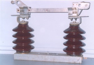
MV Outdoor Off-Load Isolator Switch
(Alternating current disconnector)
TECHNICAL SPECIFICATION
- Scope
- Electrical System
- Standards
- Type IST off-load isolator switch are complied with relevant requirements of the following standards together with all current amendments;
- IEC62271-102:2003 :High-voltage alternating-current disconnectors and earthing switches
- IEC60129:1984 :Alternating current disconnectors and earth switches
- IEC 60265-1:1998 :High voltage switches - Part 1:Switches for rated
- IEC 60694: 1996 :Common specifications for high-voltage switchgear and
- IEC 60815:1986 :Guide for the selection of insulators in respect of
- BS EN ISO 1461 :Hot dip galvanized coatings on fabricated iron and
4.0 Construction
4.1 General
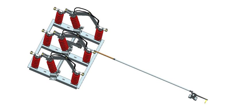
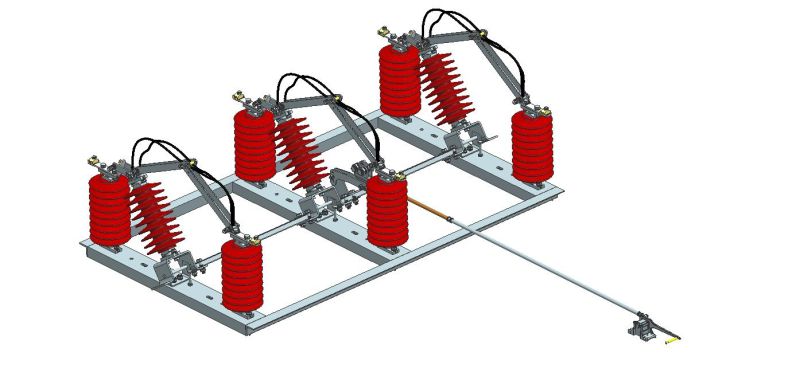
4.1.1 Type IST off-load isolator switchs are the vertical/Horizontal mounting
Type for mounting on a single or H-pole structure for overhead
lines or feeders from the energized sections.
4.1.2 Type IST off-load isolator switchs are compatible and ready for
installation on tubular steel poles and spun concrete poles.
4.1.3 The design are of an air insulated "rocking insulator"
type with two fixed insulator posts and one moving
insulator post per phase.
4.1.4 All steel and iron parts shall be galvanized to protect from corrosion as
per BS EN ISO 1461
4.1.5 Type IST off-load isolator switchs are equipped with a single operating mechanism and suitable coupling bars that shall operate all phases simultaneously and that independent operations of each
pole,irrespective of the state of the other poles,is not permitted
SPECIFICATIONS
| i. Rated Voltage | 12kV | 24KV | 36KV | ||
| ii. Rated Continuous Current Carrying Capacity |
Not Less Than 400A Up to 630A | ||||
| iii. Rated Short-Time Withstand Current (rms) | 12KV | 24KV | 36KV | ||
| >=20KA / 3 sec |
>=25KA/ 3 sec |
||||
| iv. Lightning Impulse Withstand Voltage (peak) -To earth and between poles min max |
12KV | 24KV | 36KV | ||
| 60KV 75KV |
95KV 125KV |
145KV 170KV |
|||
| -Across the isolating distance min max |
70KV 85KV |
110KV 145KV |
165KV 195KV |
||
| v. Power Frequency Withstand Voltage(r.m.s) -To earth and between poles |
12KV | 24KV | 36KV | ||
| 28KV |
50KV |
70KV |
|||
| -Across the isolating distance | 32KV | 60KV | 80KV | ||
| vi. Average Ambient Temperature (Maximum) |
28ºC (40ºC) |
||||
| i. Humidity Range | 0-100% | ||
| ii. Preferred Altitude Requirement | Up to 1,800m | ||
| iii. Insulators Total Creepage Distance (mm) Min Max |
12KV | 24KV | 36KV |
| 192 | 384 | 576 | |
| 465 |
600 | 900 | |
1.1 Operation
1.1.1 Type IST off-load isolator switchs are designed to provide a smooth,
Lightweight action requiring minimum maintenance.
1.1.2 The complete operating mechanism parts are sufficiently
Insolated from live parts, and grounded for the safety of the operator.
The operating mechanism shall be of robust,adjustable design with padlock facility in either the "OPEN" and "CLOSE" positions.
1.1.3 The complete operating mechanism are comed complete with an
Operating handle and shall be designed for steady manual operation
From ground level.
1.1.4 The insulation for the operating mechanism handle are sufficient
For the safety of the operations and preferably incorporated with an
Anti-slip grip.
1.1.5 The vertical drive rod is suitable length and shall be provided
With facilities to extend or reduce the length. Suitable couplings and operating rod guides shall be supplied with each operating mechanism.
1.1.6 If possible, it can be designed that the operating mechanism handle
use for both LEFT and RIGHT hand operations. The direction
Of the operations are clearly indicated on the operating mechanism.
1.1.7 Type IST off-load isolator switchs are designed to prevent unwanted
Operations such that:
1.1.7.1 Type IST off-load isolator switchs OPEN or CLOSE position are
remain constant despite:
a. forces arising from gravity,vibration or reasonable shock
b. accidental touching of the connecting rods or operating
devices
c. electromagnetic forces
1.1.1.1 Type IST off-load isolator switchs have provisions to prevent
Unauthorized operations
1.1.2 The OPEN or CLOSE position of the Off-Load Isolator Switch are
Easy to see from ground level by:
1.1.2.1 having a visible gap or isolating distance
1.1.2.2 having a reliable indicating device of the position of the movable
contacts.
1.1.3 Type IST off-load isolator switchs have adequate mechanical
Strength on its terminal to withstand the total forces,including
Wind loading and electromagnetic forces, related to its application
And rating,without reduction of its reliability or current carrying once
It has been installed vertically on single or H-pole structure.
1.2 Grounding
An earth terminal stud with a minimum size M12 shall be provided for the
Grounding of the operating mechanism, the terminal is marked with the
"earth" symbol.
1.3 Insulator
The materials for the insulator is silicon rubber or Porcelain, Other composite material Such as EPDM and porcelain can be Choosed.
1.4 Stationary and Moving Contacts
1.4.1 The main current carrying contacts are designed to ensure good
Electrical conductivity and to minimize pitting during operation. The
Design shall also ensure that a constant pressure is applied uniformly
Between the moving and fixed contacts.
1.4.2 The contacts are easily replaced without the need for re-alignment
Or adjustment.
1.4.3 The preferred material for the contact surfaces that are designed to
Carry the current is silver tipped or other suitable conducting material
With a minimum thickness of 15 μm.
1.1.1 The design and position of the main contacts is avoid the accumulation of dirt.
4.6 Flexible Connections
Electrical continuity to the moving contact is by means of a flexible connection that is corrosion resistant and preferably able to withstand at least up to 1,000-2000 fault-free operations. The flexible connection is insulated or laminated to prevent encroachment from animals or vegetations.
4.7 Terminals
4.7.1 The clamping and main terminal surfaces are compatible with both copper and aluminum conductor.
4.7.2 The terminals are designed such that they are capable of accepting multiple ranges of compression connectors.
4.7.3 The conductor terminals are suitable for stranded copper or aluminum cables.
2.0 Markings
Type IST off-load isolator switchs is clearly marked as follows:
i. Manufacturer's name or trade mark, type and identification
ii. Rated Voltage, Continuous Current, and Frequency
iii. Short-Time Withstand Current(r.m.s)
iv. Relevant Standards
v. The acronym of Customer's
vi. Customer's Contact Number
6.0 Inspection and Testing
6.1 General Requirements
6.1.1 We ensure that the product is inspected and tested at all stages of manufacturing in accordance with the requirements as stipulated in this specification,
6.1.2 We allow the representative of Customer or its appointed Quality Agents access to all production facilities necessary for the manufacturer of this product, at all reasonable times. The manufacturer is responsible to maintain all Quality and Test records for a minimum period of five (5) years.Customer and / or its appointed agents reserve the right to inspect these records as and when deem necessary.
6.1.1 During such inspection, any corrective actions necessary are complied with within the scope of this specification.
6.1.2 The tests are carried out in accordance to the standards as stipulated in Clause 3.0 and any additional requirement as stated in this specification.
6.2 Type Test
6.2.1 Type IST off-load isolator switchs had passed the type tests in accordance to IEC62271-102, IEC 60265-1 (or equivalent), IEC 60694 (or equivalent) and other related amendments,
a. Dielectric test per Clause IEC 62271-102-2001 Ed 1.0 2001-12
b. Measurement of resistance of the main circuit as per Clause IEC 62271-1-2007
c. Temperature rise tests as per Clause IEC 62271-102-2001
d. Short-time withstand current and peak withstand current tests as per Clause IEC 62271-102
e. Mechanical operation tests as per Clause 6.102 IEC 60265-1
Type Tests for items a,b,c&e as mentioned in Clause 7.2.1 above are conducted at an accredited independent laboratory and
6.2.2 Type Tests for items d as mentioned in Clause 7.2.1 above is conducted at an STL or STLA laboratory CPRI INDIA
6.3 Routine Tests
Routine tests are carried out by the manufacturer on all products in the finished state or, where appropriate, during the manufacturing processes. The routine test that are made on Type IST off-load isolator switchs are:-
i. Dielectric test per Clause IEC 62271-102
ii. Measurement of resistance of the main circuit IEC 62271-102
iii. Design and visual check as per IEC 62271-102
iv. Mechanical operation tests per Clause IEC 62271-102
7.0 Quality Control
We are arleady set up and implement a good quality management system. This system shall be inspect/audited by The customer appointed Quality Audit Agent before the commencement of any new contract and subsequently at agreed regular interval to ascertain the proper implementation of the quality management system.
